Why Engineering Knowledge Walks Out the Door
Why Engineering Standardization Often Fails—and How to Make It Stick
Engineer-to-Order Doesn't Have to Mean Starting from Scratch
 LOGIN |  REGISTER

SmartDesignServer

The Solution for Rapid Customization

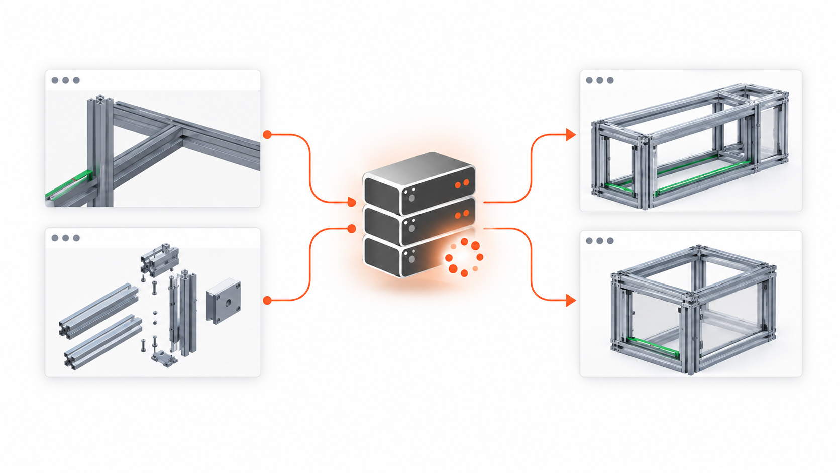
SmartDesignServer is a software program which enables Creo to become a complete on-line Design-to-Order system, without the need for lengthy and costly development. It provides the communication pathway needed to develop integrated automation platforms and manage the data communication between these different applications.

A single Creo user can manually create a generic model with related documentation and geometry which SmartDesignServer can use to generate different versions of a product. Automated parts and assemblies make it possible to manage features and components to rebuild geometry.  New users or even the sales team can make predefined changes to complex models without first having to sort through the entire design to find the correct feature or dimension to change.

Key Features

  • Complete Design-to-Order system with integration Creo to enterprise systems
  • Lightweight
  • Streamlined Application Framework
  • No need for Creo API programming or complex client/server programming
  • Bi-directional communication between Microsoft and Creo
  • One Creo license serves multiple users
  • Fully automatic data generation in Creo
  • LAN/Internet driven

How It Works

  • Search for components graphically or by parameter info
  • A Customer or Sales Rep.. can use SDS Selector or in house  Configurator,  or any other data gathering method to make product selections
  • The web client sends the data to the SmartDesignServer, which can be anywhere (even a different continent)
  • The server compiles the necessary information using Creo, MS Word, and/or any other user accessible application
  • The deliverables are sent to the client or to pre-defined locations
  • The deliverables can be a quote, Creo Models or Drawings, PDF files, DXF files, NC Programs, shearing/cutting lists, BOM for ERP/pricing, 3D renderings, or any other type Sales or Engineering  information

Key Benefits

  • Extremely short ROI to a complete Design-to-Order system
  • Fast implementation timeline: no need for year-long development projects
  • No complex server installation, portals or databases
  • Open architecture allows for easily available talent for customization or for integration to existing infrastructure
  • Ready for future growth and upgrades - XML-based environment protects your investment in SmartDesignServer
  • Does not restrict the customization of the client UI

SDS Web Selector

Personalized Product Selection Tool

Enable your customers to adapt the components and properties of your product to a finished product which optimally meets their needs and requirements.  Logically map your components in an easy to user interface.  Integrate into your companies business systems to leverage the power to enrich the product life cycle process.  

Easy to use and implement allows your company to fully own the sales process.  SDS web selector is designed to leverage the complexity of engineered products by using Creo.

Key Features

  • Integrate business Systems to selection results
  • Lightweight
  • Increased order accuracy with visualization
  • Reduce Order Complexity with logical selection sequencing
  • Nested Ordering Capability
  • Verify Order Accuracy
  • Specific User accounts with privileges

How It Works

  • Ability to Personalize web selector to match company motifs
  • Create user accounts to allowable product selection and record order history
  • Send the resultant data strings to SmartDesignServer, which can be anywhere (even a different continent) to build CAD data
  • User can select complex engineered order to orders including nested configurations
  • The deliverables are sent to the client or to predefined locations
  • The deliverables can be a quote, Creo Models or Drawings, PDF files, DXF files, NC Programs, shearing/cutting lists, BOM for ERP/pricing, 3D renderings, or any other Sales or Engineering information

Key Benefits

  • Fast implementation timeline: no need for year-long development projects
  • No complex server installation, portals or databases
  • Open architecture allows for easily available talent for customization or for integration to existing infrastructure
  • Ready for future growth and upgrades - XML-based environment protects your investment in SmartDesignServer
  • Does not restrict the customization of the client UI

SmartAssembly for Creo

Rules Based Design Automation

SmartAssembly is a process capture tool made for designers. A Creo users can be trained to create automation applications in a simple easy to understand language. Most applications can be written in a few paragraphs

Key Features

  • Automatic creation & configuration of new parts and sub-assemblies, then automatically assembling them
  • Automatic assembly of newly created or existing parts or sub-assemblies
  • Creation of part level features
  • Support for part family tables and assembly level family tables 
  • Dimensional information provided thru user input or automatically from the program 
  • Automatic relations from analysis features when assembling a component 
  • All components and features created still have full redefine or edit definition capability 
  • When a component is removed, the associated relations are also removed
  • Rich programming flexibility – loops, conditional statements, variables, etc.
  • Manufacturing and Drawing Automation Support 
  • Works with Pro/Intralink and PDMLink

How It Works

  • Define required automation rules using features, standard components and assemblies, SmartAssembly programming, and the required GUI
  • Work either in part mode to add features or at the assembly level to add features or components
  • Define project templates and re-use the data –automatically copy, rename a top-level assembly and all drawings, parts, sub-assemblies, even manufacturing files are copied and associated to the new project
  • Use the SmartAssembly GUI to speed up all design and manufacturing tasks

Key Benefits

  • Standardization of assemblies and parts  New users can be productive in a fraction of the time
  • Productivity improvements of 50-80% are commonly recognized
  • Advanced users create designs faster allowing them to focus on the design process 
  • Re-use company standard libraries – create automation programs from existing components in hours  UDF organization – eliminates common UDF problems such as UDF naming, gph file location, or required references

SmartHardware for Creo

Find and Fix Errors on the Fly

SmartHardware creates accurate Creo models and required features, using company approved hardware and manufacturing approved rules, with a high level of efficiency and limited user interaction.

Key Features

  • Flexible hardware model library options
    • Use your existing Creo hardware models
    • Use the library of hardware components included with SmartHardware
  • Combine the SmartHardware library with your existing library and customize to your unique requirements.
    • Add any hardware type to the library environment:
    • inserts, o-rings, gears, bearings, etc…
  • Allows development of local and regional DFMA rules for any design scenario.
  • Can be easily adapted to your environment and processes
  •  Works seamlessly with Windchill/PDMLink.

How It Works

  • User selects the type of hardware to be placed, placement location, and type.
  • SmartHardware offers applicable hardware options to the user
  • User selects the specific hardware and size to use
  • SmartHardware calculates the intersecting components based on user selections, and creates the necessary hole features(threaded, clearance, thru, etc.)
  • SmartHardware suggests additional fastening hardware when required by design rules.
  • User can override suggested design criteria by making additional selections as necessary.

Key Benefits

  • Allows standardization, yet flexible design for assembly of hardware
  • Designed for rapid customization and expansion to include all library parts
  • Key component in design standardization initiatives

SmartHoleChart for Creo

Productivity Tool for Creo Drawings

SmartHoleChart is software developed for Creo that automates all aspects of creating, updating and maintaining drawing holechart tables. It utilizes geometry-based feature recognition to identify any type of rotational feature, regardless of the way it is created. SmartHolechart creates drawing tables, ASCII output files and NC programs for all hole information in Creo parts.

Key Features

  • Interactive graphical definition of hole types  
  • Definition of output parameters and dimensions  
  • Interactive graphical configuration of output format 
  • Setting of different sorting criteria with priorities  
  • Recognition of all revolved symmetric geometry elements, including imported geometry  Allows any hole orientation to be evaluated, including non-orthogonal orientations  
  • User defined parameter evaluation and mapping  Works with groups, such as UDF's, to search and document group parameters to drawing tables  
  • Control of where and how to place tables  Automatic creation of associated id notes  Interactive query of documented holes  ASCII file output of hole data  
  • NC data output of holemaking programs

How It Works

  • Define your own bore types by building on basic elements such as cylinders, cones / chamfers, radiuses and threads.  
  • Use the graphic editor to define the formatting of tables, the shown dimensions and their format, as well as all sorting criteria. 
  • You have full control of the drawing tables and notes and you can generate custom formatted output files for further use in downstream manufacturing processes. 
  •  Define the type of holes to be identified by the system (cylinders, cones, chamfers, radii, etc.) as well as the assigned names for dimensions, tolerances and parameters.  
  • Define any general feature, other than holes, to be recognized by the system through analyzing feature parameters.  
  • Using any stored holechart definition, the drawing tables are created automatically, and can be automatically updated for design changes

Key Benefits

  • Speed - faster initial drawings and faster drawing updates when design changes  
  • Eliminates errors – misidentified holes, missed holes, double documentation, duplicate grouping  
  • Eliminate nonproductive activities and errors resulting from tedious repetitive tasks for hole feature documentation  
  • Simplify manufacturing tasks – complex features are simplified and reported in a clear manner  
  • Promotes drawing standardization and captures company best practices directly