Why Engineering Knowledge Walks Out the Door
Why Engineering Standardization Often Fails—and How to Make It Stick
Engineer-to-Order Doesn't Have to Mean Starting from Scratch
 LOGIN |  REGISTER

SmartHardware for Creo

Find and Fix Errors on the Fly

SmartHardware creates accurate Creo models and required features, using company approved hardware and manufacturing approved rules, with a high level of efficiency and limited user interaction.

Key Features

  • Flexible hardware model library options
    • Use your existing Creo hardware models
    • Use the library of hardware components included with SmartHardware
  • Combine the SmartHardware library with your existing library and customize to your unique requirements.
    • Add any hardware type to the library environment:
    • inserts, o-rings, gears, bearings, etc…
  • Allows development of local and regional DFMA rules for any design scenario.
  • Can be easily adapted to your environment and processes
  •  Works seamlessly with Windchill/PDMLink.

How It Works

  • User selects the type of hardware to be placed, placement location, and type.
  • SmartHardware offers applicable hardware options to the user
  • User selects the specific hardware and size to use
  • SmartHardware calculates the intersecting components based on user selections, and creates the necessary hole features(threaded, clearance, thru, etc.)
  • SmartHardware suggests additional fastening hardware when required by design rules.
  • User can override suggested design criteria by making additional selections as necessary.

Key Benefits

  • Allows standardization, yet flexible design for assembly of hardware
  • Designed for rapid customization and expansion to include all library parts
  • Key component in design standardization initiatives

SmartHoleChart for Creo

Productivity Tool for Creo Drawings

SmartHoleChart is software developed for Creo that automates all aspects of creating, updating and maintaining drawing holechart tables. It utilizes geometry-based feature recognition to identify any type of rotational feature, regardless of the way it is created. SmartHolechart creates drawing tables, ASCII output files and NC programs for all hole information in Creo parts.

Key Features

  • Interactive graphical definition of hole types  
  • Definition of output parameters and dimensions  
  • Interactive graphical configuration of output format 
  • Setting of different sorting criteria with priorities  
  • Recognition of all revolved symmetric geometry elements, including imported geometry  Allows any hole orientation to be evaluated, including non-orthogonal orientations  
  • User defined parameter evaluation and mapping  Works with groups, such as UDF's, to search and document group parameters to drawing tables  
  • Control of where and how to place tables  Automatic creation of associated id notes  Interactive query of documented holes  ASCII file output of hole data  
  • NC data output of holemaking programs

How It Works

  • Define your own bore types by building on basic elements such as cylinders, cones / chamfers, radiuses and threads.  
  • Use the graphic editor to define the formatting of tables, the shown dimensions and their format, as well as all sorting criteria. 
  • You have full control of the drawing tables and notes and you can generate custom formatted output files for further use in downstream manufacturing processes. 
  •  Define the type of holes to be identified by the system (cylinders, cones, chamfers, radii, etc.) as well as the assigned names for dimensions, tolerances and parameters.  
  • Define any general feature, other than holes, to be recognized by the system through analyzing feature parameters.  
  • Using any stored holechart definition, the drawing tables are created automatically, and can be automatically updated for design changes

Key Benefits

  • Speed - faster initial drawings and faster drawing updates when design changes  
  • Eliminates errors – misidentified holes, missed holes, double documentation, duplicate grouping  
  • Eliminate nonproductive activities and errors resulting from tedious repetitive tasks for hole feature documentation  
  • Simplify manufacturing tasks – complex features are simplified and reported in a clear manner  
  • Promotes drawing standardization and captures company best practices directly

SmartElectrode for Creo

Design, Documentation & Manufacturing of Electrodes

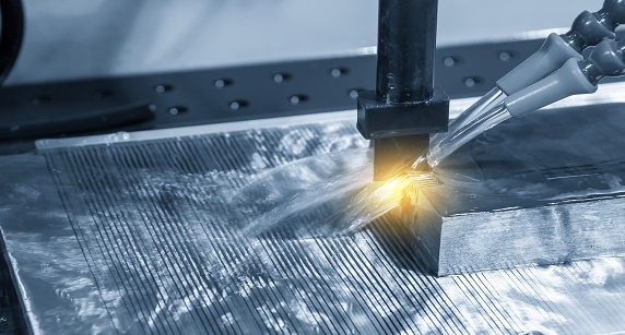
SmartElectrode is software developed for Creo that automates all aspects of extraction, design, management, documentation and manufacturing of EDM electrode.  Through its GUI-driven process, SmartElectrode guides the user through the electrode design and production process. The user simply deals with the electrode design; the burn setup sheets, and optionally the electrode drawings and machining files are all created automatically.

The GUI and process are simple while at the same time flexible, offering for the first time a sophisticated electrode design software for Creo. Within a few minutes, a complex cavity in a model is automatically extracted to form a fully featured Creo model of the electrode, along with its holder, electrode drawings, setup sheets and tool paths.
 

Key Features

  • Automatic electrode extraction
  • Automated initial electrode placement based on selected burn feature
    geometry
  • Exact placement and orientation of electrode
  • Standard catalogs of electrode blanks and holders - fully customizable and extendable
  • Single and multi-extract electrode assemblies
  • Multi-placement of the same electrode
  • Full control of burn surface and electrode refining through easy to use GUI
  • Automatic generation of burn setup sheets and electrode drawings
  • Automatic creation of Pro/NC machining files
  • Graphical display of burn areas where electrode are already designed
  • Display animation of EDM burn cycle

How It Works

  • Choose a holder and electrode blank from the available library (user extendable)
  • Graphically position, orient and fine-tune the electrode placement. The extraction is done automatically
  • Detail-design the electrode using the GUI to tweak the burn areas and neighboring areas.
  • Setup sheets, electrode drawings and manufacturing files are created automatically.

Key Benefits

  • Significant savings over the use of Creo alone
  • Consistent quality – all electrode creation follows the same process and
    feature map
  • Organizes multi-electrode jobs – eliminates electrode setup problems
  • Precise control of extension surface details gives excellent EDM surface quality
  • Immediate burn setup sheets and electrode drawings
  • Automation and organization of the process minimizes costly mistakes
  • Eliminate repetitive tasks such as creating electrode drawings, setup tables, etc.
  • Automatic machining setup with Pro/NC practically eliminates NC programming lead-time
  • Easy to learn logical process with a dynamic and easy to use interface offering unrivaled flexibility

Enforce company standards - Define standard rules per company, project or customer. Automatically set naming convention, colors, layers, default values and drawing formats.

SmartWoodDesigner

Increase Productivity in Wood Design

SmartWoodDesigner is a solution created for Creo that allows users to quickly and efficiently design wood products by capturing company processes, utilizing company part libraries and integrating manufacturing practices.

Key Features

  • Build panel parts on the fly by just picking surfaces in any design.
  • Extendable libraries:
  • Wood panel library described as: material, thickness, grain or finish.
  • Profile styles library
  • Smart hardware library-automatically bring in holes, cut-outs, shims and spacers where needed based on defined design rules.
  • Automatic wood joinery: dovetail, fingers and slots, tongue and groove, dado, pocket, butt joint, etc.

How It Works

  • Wood panels are created based on a rough design.
  • With a click of a button, fixed panels are easily converted to moveable doors or drawers in sub-assemblies.
  • User selects hardware components--creation of all necessary cuts and other features in wood panels is done automatically.
  • With integrated nesting, workpiece sizes, margins between parts, and machine cuts are automatically created.
  • NC machining tool paths are created automatically.

Key Benefits

  • Eliminates non-value added repetitive work--freeing up time for more creative work.
  • The user works faster with a set of wood specific features.
  • Provides a high level of predictability.
  • Significantly reduces panel creation, joinery design, and hardware placement time and effort.
  • Allows the user to easily design variations from originals.
  • Produce the NC tool path in drastically reduced time.

Smart Weld 3D for Creo

3D Weld Geometric Data in a Flash

SmartWeld 3D, a Creo solution, allows users to quickly and efficiently add 3D weld information to their designs by capturing and implementing company design and manufacturing standards.

Key Features

  • Quickly build weld trajectories on the fly using existing geometry.
  • Define the weld type, size, etc.
  • Any weld type can be made available including fillet, groove, and spot welds.
  • Continuous, intermittent, dual-side, and non-standard weld types are supported.
  • Information can be outputted in a variety of ways for  end users and manufacturing processes.
  • Automatically generates 2D weld symbols and data for robotic welding.

How It Works

  • User defines the start and end of the weld. 
  • User is presented with a variety of inputs and guides based on existing model geometry
  • User makes selections, and all necessary weld geometry is created on the fly by SmartWeld.
  • SmartWeld leads users in generation of 3D weld data.
  • Weld symbols are created on the fly, and data is fully parametric.
  • Generates weld parts where weld geometry is stored.

Key Benefits

  • Rapid customization to meet the needs of your company.
  • Eliminate guess and design errors when designing welds.
  • 2D weld symbols provide accurate visual cues and exact measurement data for manufacturing.
  • 3D geometry provides accurate volume and weight calculations.
  • Produces NC paths for robotic welding directly from existing geometry.
  • Costing can include more accurate variables.

More Articles …